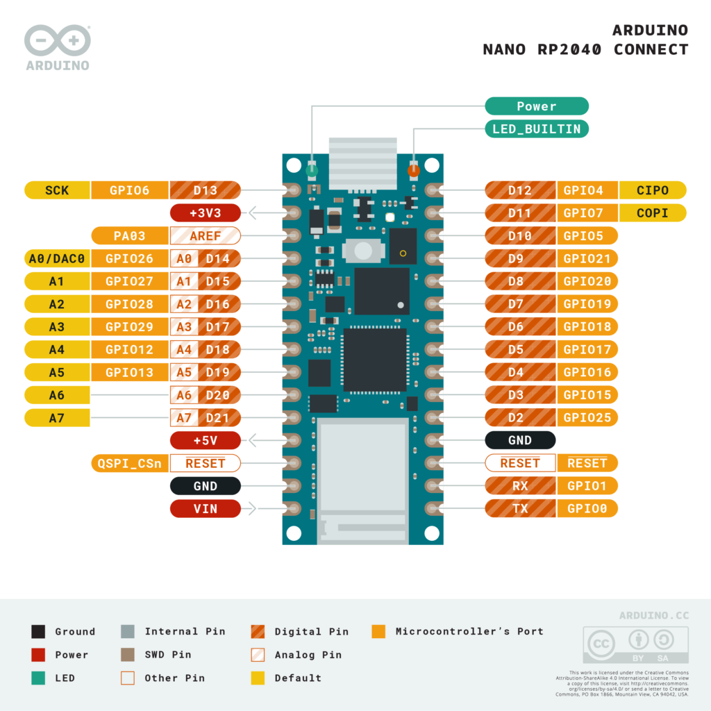
In this article we look at the LSM6DSOX sensor which is fitted on the Arduino Nano RP2040 Connect
Sensor Information
Description
The LSM6DSOX is a system-in-package featuring a 3D digital accelerometer and a 3D digital gyroscope boosting performance at 0.55 mA in high-performance mode and enabling always-on low-power features for an optimal motion experience for the consumer. The LSM6DSOX supports main OS requirements, offering real, virtual and batch sensors with 9 kbytes for dynamic data batching.
ST’s family of MEMS sensor modules leverages the robust and mature manufacturing processes already used for the production of micromachined accelerometers and gyroscopes. The various sensing elements are manufactured using specialized micromachining processes, while the IC interfaces are developed using CMOS technology that allows the design of a dedicated circuit which is trimmed to better match the characteristics of the sensing element.
The LSM6DSOX has a full-scale acceleration range of ±2/±4/±8/±16 g and an angular rate range of ±125/±250/±500/±1000/±2000 dps.
The LSM6DSOX fully supports EIS and OIS applications as the module includes a dedicated configurable signal processing path for OIS and auxiliary SPI, configurable for both the gyroscope and accelerometer. The LSM6DSOX OIS can be configured from the Auxiliary SPI and primary interface (SPI / I²C & MIPI I3CSM).
High robustness to mechanical shock makes the LSM6DSOX the preferred choice of system designers for the creation and manufacturing of reliable products. The LSM6DSOX is available in a plastic land grid array (LGA) package.
Features
- Power consumption: 0.55 mA in combo high-performance mode
- “Always-on” experience with low power consumption for both accelerometer and gyroscope
- Smart FIFO up to 9 kbyte
- ±2/±4/±8/±16 g full scale
- ±125/±250/±500/±1000/±2000 dps full scale
- Analog supply voltage: 1.71 V to 3.6 V
- Independent IO supply (1.62 V)
- SPI / I²C & MIPI I3CSM serial interface with main processor data synchronization
- Auxiliary SPI for OIS data output for gyroscope and accelerometer
- OIS configurable from Aux SPI, primary interface (SPI / I²C & MIPI I3CSM)
- Advanced pedometer, step detector and step counter
- Significant Motion Detection, Tilt detection
- Standard interrupts: free-fall, wakeup, 6D/4D orientation, click and double-click
- Programmable finite state machine: accelerometer, gyroscope and external sensors
- Machine Learning Core
- S4S data synchronization
- Embedded temperature sensor
Parts Required
| Name | Link |
| Nano RP2040 Connect. | Arduino Nano RP2040 Connect with Headers |
Code Examples
You can install the the LSM6DSOX library, which comes with 2 examples that can be used directly with the Nano RP2040 Connect.
Accelerometer example
[codesyntax lang=”cpp”]
#include <Arduino_LSM6DSOX.h>

void setup() {
  Serial.begin(9600);
  while (!Serial);

  if (!IMU.begin()) {
    Serial.println("Failed to initialize IMU!");

    while (1);
  }

  Serial.print("Accelerometer sample rate = ");
  Serial.print(IMU.accelerationSampleRate());
  Serial.println(" Hz");
  Serial.println();
  Serial.println("Acceleration in g's");
  Serial.println("X\tY\tZ");
}

void loop() {
  float x, y, z;

  if (IMU.accelerationAvailable()) {
    IMU.readAcceleration(x, y, z);

    Serial.print(x);
    Serial.print('\t');
    Serial.print(y);
    Serial.print('\t');
    Serial.println(z);
    delay(500);
  }
}
[/codesyntax]
Gyroscope example
[codesyntax lang=”cpp”]
#include <Arduino_LSM6DSOX.h>

void setup() {
  Serial.begin(9600);
  while (!Serial);

  if (!IMU.begin()) {
    Serial.println("Failed to initialize IMU!");

    while (1);
  }

  Serial.print("Gyroscope sample rate = ");
  Serial.print(IMU.gyroscopeSampleRate());
  Serial.println(" Hz");
  Serial.println();
  Serial.println("Gyroscope in degrees/second");
  Serial.println("X\tY\tZ");
}

void loop() {
  float x, y, z;

  if (IMU.gyroscopeAvailable()) {
    IMU.readGyroscope(x, y, z);

    Serial.print(x);
    Serial.print('\t');
    Serial.print(y);
    Serial.print('\t');
    Serial.println(z);
    delay(500);
  }
}
[/codesyntax]
Output
Open the serial monitor and you see output something like this
-0.04 -0.08 1.00
-0.08 -0.21 1.01
-0.55 -0.18 -0.10
-0.15 0.80 0.96
Links
https://www.st.com/resource/en/datasheet/lsm6dsox.pdf