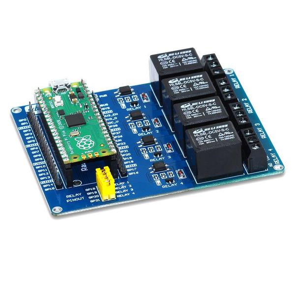
The Raspberry Pi Pico Relay Board from sbcomponents allows your Raspberry Pi Pico to control up to 4 devices with loads up to 240V AC / 7A or 30V DC / 10A.
The 4 channels have an opto-isolator, here is what an opto-isolator does
An opto-isolator (also called an optocoupler, photocoupler, or optical isolator) is an electronic component that transfers electrical signals between two isolated circuits by using light.
Opto-isolators prevent high voltages from affecting the system receiving the signal. Commercially available opto-isolators withstand input-to-output voltages up to 10 kV and voltage transients with speeds up to 25 kV/μs.
A common type of opto-isolator consists of an LED and a phototransistor in the same opaque package. Other types of source-sensor combinations include LED-photodiode, LED-LASCR, and lamp-photoresistor pairs. Usually opto-isolators transfer digital (on-off) signals, but some techniques allow them to be used with analog signals.
Each relay also includes an indicator LED for easy debugging. Relay control jumpers allow users to control the relays by custom pins other than the default pins.
The board uses GP18, Gp19, GP20 and GP21 to control the individual relays – so these will not be available for other devices, sensors or modules
To switch the Relay On set the output to 1, To switch the Relay Off set the output to 0
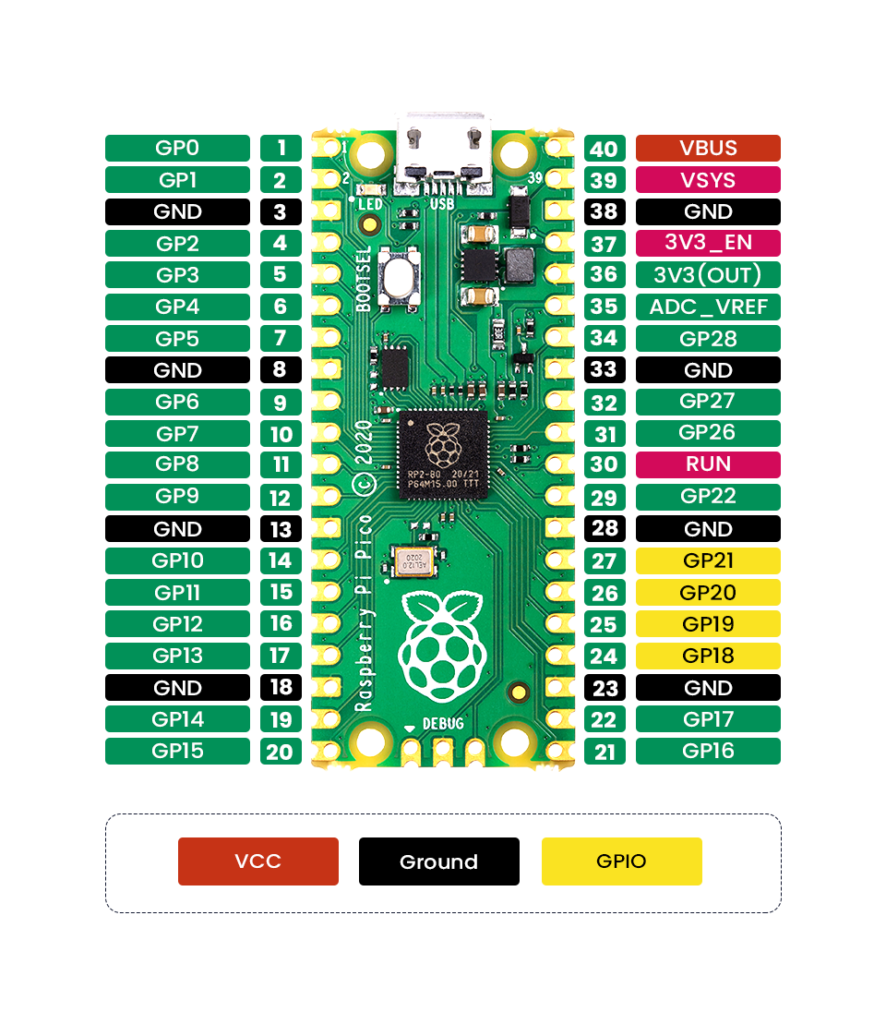
Relay_board pinout
Features
4 High-quality Relay and loads up to 240V AC @ 7A, 30V DC @ 10A
opto-isolator (CTR: 50-600% at IF =5mA, VCE =5V)
Indicator LEDs for Relay output status
Relay control jumpers allow the user to control the relays by custom pins other than the default pins
Female header for fitting a Raspberry Pi Pico (with male headers attached)
Male headers break out all Pico GPIO pins for prototyping with jumper wires
Specifications
- Channels – 4
- Operating Voltage – 5V
- Switching Voltage (VAC) – 7A/ 250V
- Switching Voltage(VDC) – 10A/ 30V
- Dimensions – 58 x 21 mm
Code
[codesyntax lang=”python”]
from machine import Pin
import utime

relay1 = Pin(18, Pin.OUT)
relay2 = Pin(19, Pin.OUT)
relay3 = Pin(20, Pin.OUT)
relay4 = Pin(21, Pin.OUT)

def AllOn():
    relay1.value(1)
    relay2.value(1)
    relay3.value(1)
    relay4.value(1)

 def AllOff():
    relay1.value(0)
    relay2.value(0)
    relay3.value(0)
    relay4.value(0)

while True:
    AllOn()
    utime.sleep(1)
    AllOff()
    utime.sleep(1)
    relay1.toggle()
    utime.sleep(0.5)
    relay2.toggle()
    utime.sleep(0.5)
    relay3.toggle()
    utime.sleep(0.5)
    relay4.toggle()
    utime.sleep(0.5)
[/codesyntax]
Purchase
Links
There is a C++ example – https://github.com/sbcshop/Raspberry-Pi-Pico-Relay-Board