The Maker Pi RP2040 board is aimed at robotics with features such as a 2-channel DC motor driver, 4 servo motor ports, 7 Grove I/O connectors, and lots of LEDs connected to the I/O pins which can be used for troubleshooting.
The DC motor driver on the board is able to control two brushed DC motors or a single bipolar/unipolar stepper motor from 3.6V to 6V, providing up to 1A current per channel continuously..
The built-in test buttons and motor output LEDs allow a quick and easy test of the motor driver without writing any code.
By default CircuitPython is loaded onto the Maker Pi RP2040 and it runs a simple demo program right out of the box for testing your board.
The demo program does the following
- On startup:
- play a melody tune
- perform a sequential LED lighting (blue LEDs)
- Forever loop:
- RGB (Neopixel) LEDs perform color fading
- Press GP20 push button:
- light up all blue LEDs
- run DC Motor 1 forward and DC Motor 2 backward, both at 50% speed
- move all Servo motors to 0 degree
- Press GP21 push button:
- turn off all blue LEDs
- stop both DC Motor 1 & 2
- move all Servo motors to 180 degree
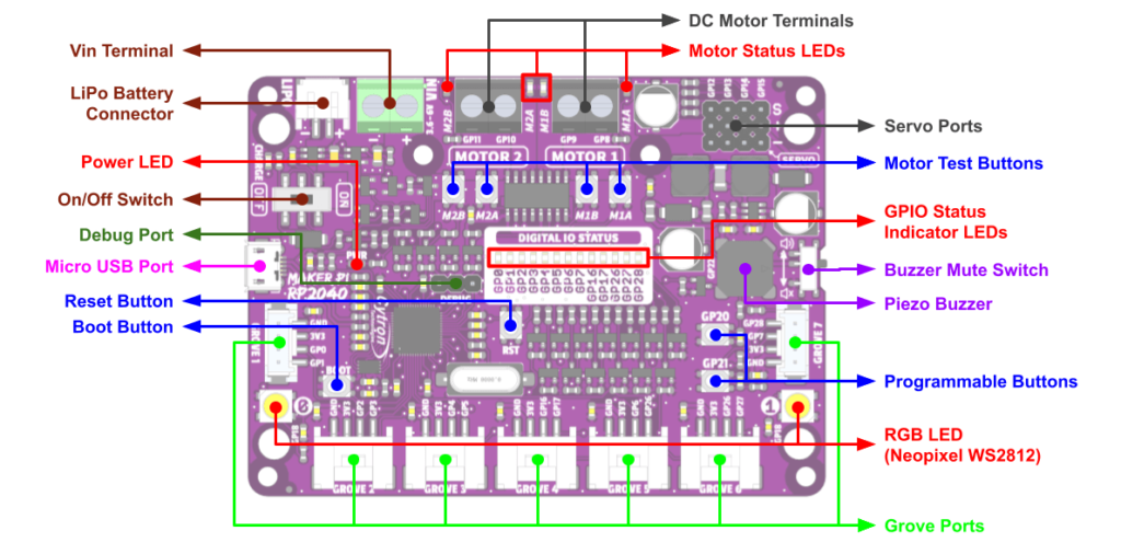
| Function | Description |
| Vin Terminal | Connect to any power source within 3.6 – 6V. |
| LiPo Battery Connector | Connect to Single Cell LiPo / Li-Ion Battery
The battery is rechargeable via USB.
∗ The battery is protected from overcharged and over discharged. If the board cannot be turned on when the battery is connected, please charge the battery to activate the battery protection circuit. |
| Power LED | Turn on when powered up. |
| On/Off Switch | Turn on/off the power. |
| Debug Port | Debugging port of the RP2040. |
| Micro USB Port | Used for upload programs from PC. Can also be used to power up the board. |
| Reset Button | Press to reset the RP2040. |
| Boot Button | Press and hold this button while resetting the RP2040 will enter the bootloader mode. Used to load the Micropython/Circuitpython or custom C/C++ firmware. |
| Function | Description | ||||||||||||||||||||||||||||||||||||||||||||||||||||||||||||||||||||||||||||||||||||||||||||||||||
| Grove Ports | Connect to external Grove modules.
|
||||||||||||||||||||||||||||||||||||||||||||||||||||||||||||||||||||||||||||||||||||||||||||||||||
| RGB LEDs (WS2812) | User programmable WS2812B RGB LED. Connected to GP18. | ||||||||||||||||||||||||||||||||||||||||||||||||||||||||||||||||||||||||||||||||||||||||||||||||||
| Programmable Buttons | Accessible from the user program. Connected to GP20 and GP21 | ||||||||||||||||||||||||||||||||||||||||||||||||||||||||||||||||||||||||||||||||||||||||||||||||||
| Piezo Buzzer | Can be used to play tone or melody. Connected to GP22. | ||||||||||||||||||||||||||||||||||||||||||||||||||||||||||||||||||||||||||||||||||||||||||||||||||
| Buzzer Mute Switch | Used to mute the piezo buzzer. | ||||||||||||||||||||||||||||||||||||||||||||||||||||||||||||||||||||||||||||||||||||||||||||||||||
| GPIO Status LEDs | LED indicators for RP2040 GPIOs on Grove Ports. Turn on when the GPIO state is high. | ||||||||||||||||||||||||||||||||||||||||||||||||||||||||||||||||||||||||||||||||||||||||||||||||||
| Motor Test Buttons | Press to test the functionality of the motor driver. Motor will run at full speed.
● MxA : Forward* ● MxB : Backward* |
||||||||||||||||||||||||||||||||||||||||||||||||||||||||||||||||||||||||||||||||||||||||||||||||||
| Servo Ports | Connectors for 4 x RC servo motors. Signal is connected to GP12, GP13, GP14 and GP15. V+ voltage is equal to power source voltage. | ||||||||||||||||||||||||||||||||||||||||||||||||||||||||||||||||||||||||||||||||||||||||||||||||||
| Motor Status LEDs | Turn on when the motor is running.
● MxA : Forward* ● MxB : Backward* |
||||||||||||||||||||||||||||||||||||||||||||||||||||||||||||||||||||||||||||||||||||||||||||||||||
| DC Motor Terminals | Connect to the motor terminal.Motor voltage at full speed is equal to power source voltage. Motor direction is dependent on the polarity.
|
Features:
- Powered by Raspberry Pi RP2040
- Dual-core Arm Cortex-M0+ processor
- 264KB internal RAM
- 2MB of Flash memory
- the exact same specifications with Raspberry Pi Pico
- Robot controller board
- 4 x Servo motors
- 2 x DC motors with quick test buttons
- Versatile power circuit
- Automatic power selection: USB 5V, LiPo (1-cell), or Vin (3.6-6V)
- Built-in 1-cell LiPo/Li-Ion charger (over-charged & over-discharged protection)
- Power on/off switch
- 13 x Status indicator LEDs for GPIO pins
- 1 x Piezo buzzer with mute switch
- 2 x Pushbutton
- 2 x RGB NeoPixel LED
- 7 x Grove ports (flexible I/O options: digital, analog, I2C, SPI, UART…)
- Preloaded with CircuitPython by default
Specifications
| No | Parameters | Min | Max | Unit | |
| 1 | Power Input Voltage (USB, LiPo or VIN) * | 3.6 | 6 | V | |
| 2 | Digital Input Voltage | Low Level | -0.3 | 0.8 | V |
| High Level | 2.0 | 3.6 | V | ||
| 3 | Digital Output Voltage | Low Level | 0 | 0.5 | V |
| High Level | 2.6 | 3.3 | V | ||
| 4 | Analog Input Voltage | 0 | 3.3 | V | |
| 5 | Vmotor & Vservo (Only USB is connected) | VUSB – 0.4 | V | ||
| 6 | Vmotor & Vservo (Only either one of LiPo or VIN is connected) | VLiPo or VIN | V | ||
| 7 | Vmotor & Vservo (USB and LiPo are connected) | VUSB – 0.4 | V | ||
| 8 | Vmotor & Vservo (USB and VIN are connected) |
VIN < VUSB | VUSB – 0.4 | V | |
| VIN > VUSB
and VIN – VUSB < 0.6 |
VIN – 0.4 | V | |||
| VIN – VUSB > 0.6 | VIN | V | |||
| 9 | Maximum DC Motor Current (Per Channel) | Continuous | – | 1 | A |
| Peak (< 5 seconds) | – | 1.5 | A | ||
| 10 | Total +3V3 Output Current (Grove Ports) | – | 300 | mA | |
| 11 | Operating Temperature | -20 | 85 | ℃ | |
Purchase
Links
- Getting Started with Maker Pi RP2040 & Example Code
- Maker Pi RP2040 Datasheet
- Maker Pi RP2040 Schematic
- Maker Pi RP2040 VS. Maker Pi Pico comparison table
- CircuitPython for Maker Pi RP2040
- 3D CAD