In this article we connect a ADS1015 analog-to digital converter to a Raspberry Pi Pico running Circuitpython
Sensor Information
The ADS1013, ADS1014, and ADS1015 devices (ADS101x) are precision, low-power, 12-bit, I2C compatible, analog-to digital converters (ADCs) offered in an ultra-small, leadless, X2QFN-10 package, and a VSSOP-10 package.
The ADS101x devices incorporate a low-drift voltage reference and an oscillator.
The ADS1014 and ADS1015 also incorporate a programmable gain amplifier (PGA) and a digital comparator.
These features, along with a wide operating supply range, make the ADS101x well suited for power- and space-constrained, sensor measurement applications.
The ADS101x perform conversions at data rates up to 3300 samples per second (SPS). The PGA offers input ranges from ±256 mV to ±6.144 V, allowing precise large- and small-signal measurements.
The ADS1015 features an input multiplexer (MUX) that allows two differential or four single-ended input measurements. Use the digital comparator in the ADS1014 and ADS1015 for under- and overvoltage detection.
The ADS101x operate in either continuousconversion mode or single-shot mode. The devices are automatically powered down after one conversion in single-shot mode; therefore, power con
Features
Ultra-Small X2QFN Package: 2 mm × 1.5 mm × 0.4 mm
12-Bit Noise-Free Resolution
Wide Supply Range: 2.0 V to 5.5 V
Low Current Consumption: 150 μA (Continuous-Conversion Mode)
Programmable Data Rate: 128 SPS to 3.3 kSPS
Single-Cycle Settling
Internal Low-Drift Voltage Reference
Internal Oscillator
I2C Interface: Four Pin-Selectable Addresses
Four Single-Ended or Two Differential Inputs (ADS1015)
Programmable Comparator (ADS1014 and ADS1015)
Parts Required
| Name | Link |
| Pico | Raspberry Pi Pico Development Board |
| ADS1015 | CJMCU-ADS1015 ultra-compact 12 -precision ADC module |
| Connecting cables | Aliexpress product link |
Schematic/Connection
I used the ADS1015 module – I have not connected anything to the A0 connection in the schematic
Black for GND
Red for V+
Blue for SDA
Yellow for SCL
So color coded for ease of use, this layout shows a connection to the module
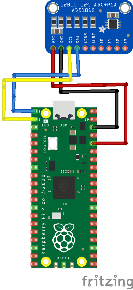
rp2040 and ADS1015
Code Example
I used Thonny for development
The following is based on a library , I copied the adafruit_ads1x15 folder whioch contains various libraries for this device to the lib folder on my Feather M0 Express – https://circuitpython.org/libraries
This is the basic example which comes with the library
[codesyntax lang=”python”]
import time
import board
import adafruit_ads1x15.ads1015 as ADS
from adafruit_ads1x15.analog_in import AnalogIn
import busio

# Create sensor object, communicating over the board's default I2C bus
i2c = busio.I2C(scl=board.GP1, sda=board.GP0) # uses board.SCL and board.SDA
# Create the ADC object using the I2C bus
ads = ADS.ADS1015(i2c)

# Create single-ended input on channel 0
chan = AnalogIn(ads, ADS.P0)

# Create differential input between channel 0 and 1
# chan = AnalogIn(ads, ADS.P0, ADS.P1)

print("{:>5}\t{:>5}".format("raw", "v"))

while True:
    print("{:>5}\t{:>5.3f}".format(chan.value, chan.voltage))
    time.sleep(0.5)
[/codesyntax]
Output
Here is what I saw in Thonny REPL window
Links
https://www.ti.com/lit/ds/symlink/ads1015.pdf