In this article we connect a LTR329 UV Light Sensor to the Raspberry Pi Pico
Sensor Information
The LTR-329ALS-01 is a low voltage I2C digital light sensor [ALS] in a low cost miniature chipled lead-free surface mount package.
This sensor converts light intensity to a digital output signal capable of direct I2C interface. It provides a linear response over a wide dynamic range from 0.01 lux to 64k lux and is well suited to applications under high ambient brightness.
There are altogether six gain settings (1X, 2X, 4X, 8X, 48X and 96X) available for user to configure. This CMOS design and factory-set one time trimming capability ensure minimal sensor-to-sensor variations for ease of manufacturability to the end customers
Features
I2C interface (Fast Mode @ 400kbit/s)
Ultra-small ChipLED package
Built-in temperature compensation circuit
Low active power consumption with standby mode
Supply voltage range from 2.4V to 3.6V capable of 1.7V logic voltage
Operating temperature range from -30C to +70C
RoHS and Halogen free compliant
Light Sensor
Close to human eye spectral response
Immunity to IR / UV Light Source
Automatically rejects 50 / 60 Hz lightings flicker
6 dynamic range from 0.01 lux to 64k lux
16-bit effective resolution
Parts Required
The sensor you can pick up in the $6 price range – you can connect to the sensor using a standard header the classic dupont style jumper wire.
I used a Qwiic cable – since a few sensors seem to use these but this is optional
| Name | Link |
| Pico | Raspberry Pi Pico Development Board |
| LTR329 | adafruit LTR329 |
| Connecting cables | Aliexpress product link |
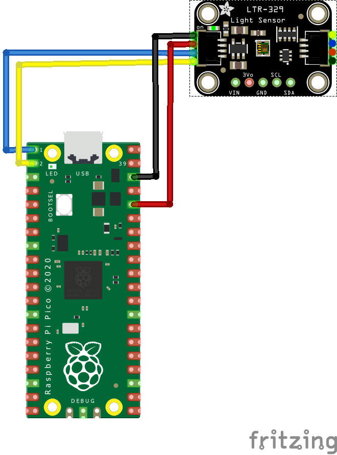
Schematic/Connection
I used the Adafruit LTR303 sensor and in this case used the Stemma connection
For the STEMMA QT cables, it uses the Qwiic convention:
Black for GND
Red for V+
Blue for SDA
Yellow for SCL
So color coded for ease of use, this layout shows a connection to the module
Code Example
I used Thonny for development and I am using Circuitpython
You will need to download and install the latest circuitpython from the citrcuitpython download site
The following is based on a library which you can download the zip bundle from https://github.com/adafruit/Adafruit_CircuitPython_Bundle/releases
Before you continue make sure your board’s lib folder or root filesystem has the adafruit_ltr329_ltr303.mpy, adafruit_bus_device, and adafruit_register files and folders copied over on the RP2040 – https://circuitpython.org/libraries
This is the basic example
import time
import board
import busio
import adafruit_ltr329_ltr303 as adafruit_ltr329

i2c = busio.I2C(board.GP1, board.GP0) # SCL, SDA
# i2c = board.STEMMA_I2C()  # For using the built-in STEMMA QT connector on a microcontroller

time.sleep(0.1)  # sensor takes 100ms to 'boot' on power up
ltr329 = adafruit_ltr329.LTR329(i2c)

# Can set the ALS light gain, can be: 1, 2, 4, 8, 48 or 96 times
# to range from 1~64 kLux to 0.01~600 Lux
ltr329.als_gain = 96
print("LTR-329 ALS gain:", ltr329.als_gain)

# Can set the ALS measurement integration time, how long the sensor
# 'looks' for light data. Default is 100ms.
# Set to: 50, 100, 150, 200, 250, 300, 350, or 400 milliseconds
# ltr329.integration_time = 50
print("LTR-329 integration time (ms):", ltr329.integration_time)

# Can set the ALS measurement rate, how often the data register updates
# Default is 500ms. Must be equal or greater than the integration time
# Set to: 50, 100, 200, 500, 1000, 2000 milliseconds
# ltr329.measurement_rate = 500
print("LTR-329 measurement rate (ms):", ltr329.measurement_rate)

# Can put into stand-by mode at any time, for low power usage
# self.active_mode = False

while True:
    # The sensor will let us know when the measurement time has
    # created a new data reading!
    if ltr329.new_als_data_available:
        # The sensor can get 'overwhelmed' by bright light if the
        # gain isn't set right, in which case the data is invalid.
        # We can check the data invalid first and toss out the reading...
        if ltr329.als_data_invalid:
            ltr329.throw_out_reading()  # perform & toss out the reading
            continue  # try again next time!

        # OR we can 'try' to do the read and get an exception if the
        # data is invalid
        try:
            # If we're using `new_als_data_available` we should
            # read both channels ONCE only! To do that use...
            visible_plus_ir, ir = ltr329.light_channels
            # this will get both channels at once! (It's also faster)

            # Now we can do various math...
            print("Visible + IR:", visible_plus_ir)
            print("Infrared    :", ir)
            print("ALS gain:   :", ltr329.als_data_gain)
            print()
        except ValueError:
            # we can also check `ltr329.als_data_invalid` if we
            # want, to verify that
            print("Light sensor data invalid, trying again!")
    time.sleep(0.1)
Output
Here is what I saw in Thonny REPL window
>>> %Run -c $EDITOR_CONTENT
LTR-329 ALS gain: 96
LTR-329 integration time (ms): 100
LTR-329 measurement rate (ms): 500
Visible + IR: 18
Infrared : 12
ALS gain: : 1

Visible + IR: 1594
Infrared : 907
ALS gain: : 96

Visible + IR: 8
Infrared : 10
ALS gain: : 96
Links
https://optoelectronics.liteon.com/upload/download/DS86-2014-0006/LTR-329ALS-01_DS_V1.5.PDF