In this article we connect a MLX90393 magnetometer to a Raspberry Pi Pico running Circuitpython
Sensor Information
The MLX90393 magnetic field sensor IC can be reprogrammed to different modes and with different settings at run-time. The sensor IC offers a 16-bit output proportional to the magnetic flux density sensed along the XYZ axes using the Melexis proprietary Triaxis® technology and also offers a temperature output signal.
These digital values are available via I2C and SPI, where the MLX90393 is a slave on the bus.
By selecting which axes are to be measured, the raw data can be used as input for further post-processing, such as for joystick applications, rotary knobs, and more complex 3D position sensing applications.
Features and benefits
Trade-off between current consumption, speed and signal noise with best-in-class Figure of Merit
Can be used to measure magnetic XYZ and temperature T or any combination thereof
Duty cycle between 0.1% and 100% (continuous burst)
Single measurement mode, burst mode and wake-up on change mode
SPI slave and/or I2C slave with 2 bits HW addressing and 5 bits SW
For certain encoder applications speed is crucial, which is possible by increasing the duty cycle to 100% (i.e. maximum current consumption) and minimizing the conversion time (i.e. higher data rate at the expense of more noise on the signal).
Other battery powered applications that only require occasional sensor readout can opt for a different trade-off: reduced duty cycle (lower current consumption) and an average conversion time for reduced noise.
Parts Required
| Name | Link |
| Pico | Raspberry Pi Pico Development Board |
| MLX90393 | MLX90393 three digital Hall sensor |
| Connecting cables | Aliexpress link |
Schematic/Connection
Black for GND
Red for V+
Blue for SDA
Yellow for SCL
So color coded for ease of use, this layout shows a connection to the module
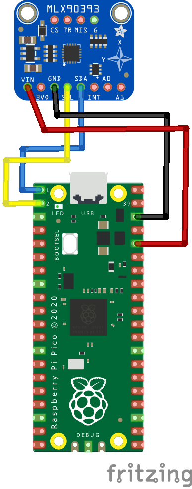
rp2040 and mlx90393
Code Example
I used Thonny for development
The following is based on a library , I copied the adafruit_mlx90393.mpy library for this device to the lib folder on my Raspberry Pi Pico – https://circuitpython.org/libraries
[codesyntax lang=”python”]
import time
import board
import busio
import adafruit_mlx90393

# Create sensor object, using the board's default I2C bus.
i2c = busio.I2C(board.GP1, board.GP0)  # SCL, SDA
SENSOR = adafruit_mlx90393.MLX90393(i2c, gain=adafruit_mlx90393.GAIN_1X)

while True:
    MX, MY, MZ = SENSOR.magnetic
    print("[{}]".format(time.monotonic()))
    print("X: {} uT".format(MX))
    print("Y: {} uT".format(MY))
    print("Z: {} uT".format(MZ))
    # Display the status field if an error occured, etc.
    if SENSOR.last_status > adafruit_mlx90393.STATUS_OK:
        SENSOR.display_status()
    time.sleep(1.0)
[/codesyntax]
Output
Here is what I saw in Thonny REPL window
[84.3]
X: -11.4 uT
Y: -142.05 uT
Z: 36.542 uT
[85.53]
X: -9.45 uT
Y: -142.2 uT
Z: 36.784 uT
[86.758]
X: 0.6 uT
Y: -135.6 uT
Z: 49.61 uT
Links
https://www.melexis.com/-/media/files/documents/datasheets/mlx90393-datasheet-melexis.pdf