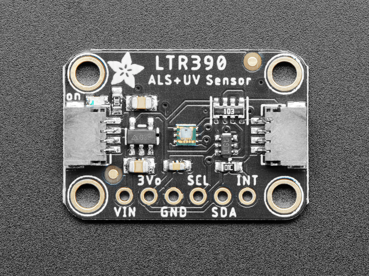
In this article we connect a LTR390 UV Light Sensor to the Raspberry Pi Pico
Sensor Information
This sensor converts light intensity to a digital output signal capable of direct I2C interface.
It provides a linear ALS response over a wide dynamic range, and is well suited to applications under high ambient brightness.
The sensor has a programmable interrupt with hysteresis to response to events and that removes the need to poll the sensor for a reading which improves system efficiency.
This CMOS design and factory-set one time trimming capability ensure minimal sensor-to-sensor variations for ease of manufacturability to the end customers.
Features
I2C interface capable of Standard mode @100kHz or Fast mode @400kHz communication; 1.8V logic compatible
Ambient Light / Ultraviolet light(UVS)Technology in one ultra-small 2x2mm ChipLED package
Very low power consumption with sleep mode capability
Operating voltage ranges: 1.7V to 3.6V
Operating temperature ranges: -40 to +85 ºC
Built-in temperature compensation circuit
Programmable interrupt function for ALS , UVS with upper and lower thresholds
RoHS andHalogen free compliant
UVS/ALS Features
- 13 to 20 bits effective resolution
- Wide dynamic range of 1:18,000,000 with linear response
- Close to human eye spectral response
- Automatic rejection for 50Hz/60Hz lighting flicker
This is the sensor that I bought
Parts Required
The sensor you can pick up in the $6 price range – you can connect to the sensor using a standard header the classic dupont style jumper wire.
I used a Qwiic cable – since a few sensors seem to use these but this is optional
| Name | Link |
| Pico | Raspberry Pi Pico Development Board |
| LTR390 | Adafruit LTR390 UV Light Sensor – Stemma QT/Qwiic |
| Connecting cables | Aliexpress product link |
Schematic/Connection
I used the Adafruit LTR390 sensor and in this case used the Stemma connection
For the STEMMA QT cables, it uses the Qwiic convention:
Black for GND
Red for V+
Blue for SDA
Yellow for SCL
So color coded for ease of use, this layout shows a connection to the module
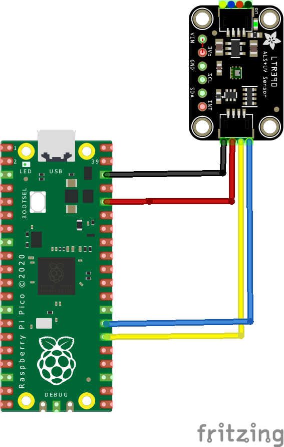
rp2040 and ltr390 layout
Code Example
I used Thonny for development and I am using Circuitpython
You will need to download and install the latest circuitpython from the citrcuitpython download site
The following is based on a library which you can download the zip bundle from https://github.com/adafruit/Adafruit_CircuitPython_Bundle/releases
Before you continue make sure your board’s lib folder or root filesystem has the adafruit_msa301.mpy, adafruit_bus_device, and adafruit_register files and folders copied over on the RP2040 – https://circuitpython.org/libraries
This is the basic example which comes with the library
import time
import board
import busio
import adafruit_ltr390

i2c = busio.I2C(scl=board.GP21, sda=board.GP20)
ltr = adafruit_ltr390.LTR390(i2c)

while True:
    print("UV:", ltr.uvs, "\t\tAmbient Light:", ltr.light)
    print("UVI:", ltr.uvi, "\t\tLux:", ltr.lux)
    time.sleep(1.0)
Output
Here is what I saw in Thonny REPL window
UV: 0 Ambient Light: 79
UVI: 0.0 Lux: 63.2
UV: 0 Ambient Light: 79
UVI: 0.0 Lux: 63.2
UV: 0 Ambient Light: 80
UVI: 0.0 Lux: 63.2
UV: 0 Ambient Light: 1
UVI: 0.0 Lux: 0.8
Links