In this article we connect a DPS310 barometric pressure sensor to a Raspberry Pi Pico running Circuitpython
Sensor Information
The pressure sensor element is based on a capacitive sensing principle which guarantees high precision during temperature changes. The small package makes the DPS310 ideal for mobile applications and wearable devices.The internal signal processor converts the output from the pressure and temperature sensor elements to 24 bit results.
Each unit is individually calibrated, the calibration coefficients calculated during this process are stored in the calibration registers. The coefficients are used in the application to convert the measurement results to high accuracy pressure and temperature values.
The result FIFO can store up to 32 measurement results, allowing for a reduced host processor polling rate. Sensor measurements and calibration coefficients are available through the serial I2C or SPI interface.
The measurement status is indicated by status bits or interrupts on the SDO pin.
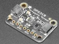
Here is the sensor I purchased from the good folks at Adafruit (via Pimoroni in the UK)
Features
- Supply voltage range 1.7V to 3.6V
- Operation range 300hPa – 1200hPa
- Sensor’s precision 0.002hPa
- Relative accuracy ±0.06hPa
- Pressure temperature sensitivity of 0.5Pa/K
- Temperature accuracy ±0.5C°
This is the sensor that I bought
Parts Required
The sensor you can pick up in the $6 price range – you can connect to the sensor using a standard header the classic dupont style jumper wire.
I used a Qwiic cable – since a few sensors seem to use these but this is optional
| Name | Link |
| Pico | Raspberry Pi Pico Development Board |
| DPS310 | AliExpress link |
| Connecting cables | Aliexpress product link |
Schematic/Connection
I used the Adafruit PCT2075 sensor and in this case used the Stemma connection
For the STEMMA QT cables, it uses the Qwiic convention:
Black for GND
Red for V+
Blue for SDA
Yellow for SCL
So color coded for ease of use, this layout shows a connection to the module
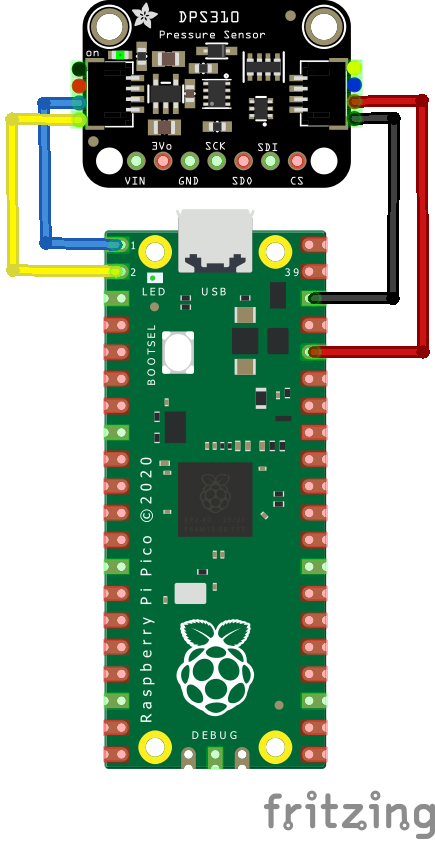
rp2040 and dps310
Code Example
I used Thonny for development
The following is based on a library , I copied the adafruit_dps310.mpy library for this device to the lib folder on my Raspberry Pi Pico – https://circuitpython.org/libraries
This is the basic example which comes with the library
[codesyntax lang=”python”]
import time
import board
import adafruit_dps310
import busio

# Create sensor object, communicating over the board's default I2C bus
i2c = busio.I2C(scl=board.GP1, sda=board.GP0)
dps310 = adafruit_dps310.DPS310(i2c)

while True:
    print("Temperature = %.2f *C" % dps310.temperature)
    print("Pressure = %.2f hPa" % dps310.pressure)
    print("")
    time.sleep(1.0)
[/codesyntax]
Output
Here is what I saw in Thonny REPL window
Temperature = 21.09 *C
Pressure = 996.13 hPa
Temperature = 21.72 *C
Pressure = 996.24 hPa
Temperature = 21.99 *C
Pressure = 996.06 hPa
Temperature = 22.15 *C
Pressure = 996.12 hPa
Links