In this article we connect a MCP9808 digital temperature sensor to a Raspberry Pi Pico running Circuitpython
Sensor Information
The MCP9808 digital temperature sensor converts temperatures between -40°C and +125°C to a digital word with ±0.5°C (max.) accuracy. The MCP9808 comes with user-programmable registers that provide flexibility for temperature sensing applications.
The registers allow user-selectable settings such as Shutdown or low-power modes and the specification of temperature Event and Critical output boundaries. When the temperature changes beyond the specified boundary limits, the MCP9808 outputs an Event signal.
The user has the option of setting the event output signal polarity as an active-low or active-high comparator output for thermostat operation, or as temperature event interrupt output for microprocessor-based systems. The event output can also be configured as a Critical temperature output.
This sensor has an industry standard 2-wire, SMBus and Standard I2C™Compatible compatible (100kHz/400kHz bus clock) serial interface, allowing up to eight sensors to be controlled in a single serial bus.
Features
- ±0.25°C (typical) from -40°C to +125°C
- ±0.5°C (maximum) from -20°C to +100°C
- 0.5°C, 0.25°C, 0.125°C, 0.0625°C
- Temperature Window Limit
- Critical Temperature Limit
- User Programmable Temperature Alert Output
- Operating Voltage Range: 2.7V to 5.5V
- Operating Current: 200 µA (typical)
- Shutdown Current: 0.1 µA (typical)
- 2-wire Interface: I2C/SMBus Compatible
Parts Required
| Name | Link |
| Pico | Raspberry Pi Pico Development Board |
| MCP9808 | MCP9808 I2C Breakout Board Module |
| Connecting cables | Aliexpress link |
Schematic/Connection
I used the Adafruit MCP9808 sensor
Black for GND
Red for V+
Blue for SDA
Yellow for SCL
So color coded for ease of use, this layout shows a connection to the module
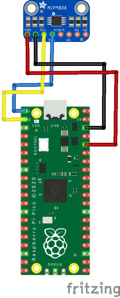
rp2040 and mcp9808
Code Example
I used Thonny for development
The following is based on a library , I copied the adafruit_mcp9808.mpy library for this device to the lib folder on my Raspberry Pi Pico – https://circuitpython.org/libraries
This is the basic example which comes with the library
[codesyntax lang=”python”]
import time
import board
import adafruit_mcp9808
import busio

i2c = busio.I2C(scl=board.GP1, sda=board.GP0) # uses board.SCL and board.SDA

# To initialise using the default address:
mcp = adafruit_mcp9808.MCP9808(i2c)

# To initialise using a specified address:
# Necessary when, for example, connecting A0 to VDD to make address=0x19
# mcp = adafruit_mcp9808.MCP9808(i2c_bus, address=0x19)

while True:
    tempC = mcp.temperature
    tempF = tempC * 9 / 5 + 32
    print("Temperature: {} C {} F ".format(tempC, tempF))
    time.sleep(2)
[/codesyntax]
Output
Here is what I saw in Thonny REPL window
Temperature: 16.875 C 62.375 F
Temperature: 16.875 C 62.375 F
Temperature: 19.125 C 66.425 F
Temperature: 21.5 C 70.7 F
Temperature: 22.375 C 72.275 F
Temperature: 22.5 C 72.5 F
Links
https://ww1.microchip.com/downloads/en/DeviceDoc/25095A.pdf